


Guide to 3D Metrology Files, Models, & Methods
Common 3D Metrology File Types
There are many types of files associated with 3D Scanning, CMM, and Reverse Engineering Technologies.
The purpose of this post is to offer a quick guide to these file formats and methods.
Point Cloud
Point clouds are the rawest form of data and are made up of numerical point locations (XYZ) that represent features or form. These data sets can range from just a few points to millions.
Point clouds are saved as typically saved as .txt files and can be imported or exported in most softwares. However, many will struggle to use and manipulate these data sets, especially if they are large.

Mesh/ Polygonal File
Mesh or polygonal files are point cloud data sets that have been optimized and surfaced, or meshed, by connecting all of the points with triangular surfaces. Hardware capabilities and software settings and tools play a significant role in scan quality, correction, and manipulation.
There are many file types for mesh files and not all are equal. Some, like .stl, are nearly universal, but are large in file size and retain less information. When working with marketing companies, their preference seems to be .obj. .ply is Haven Metrology’s preferred file type due the retention of more information like color, vectors, and significantly smaller file sizes.

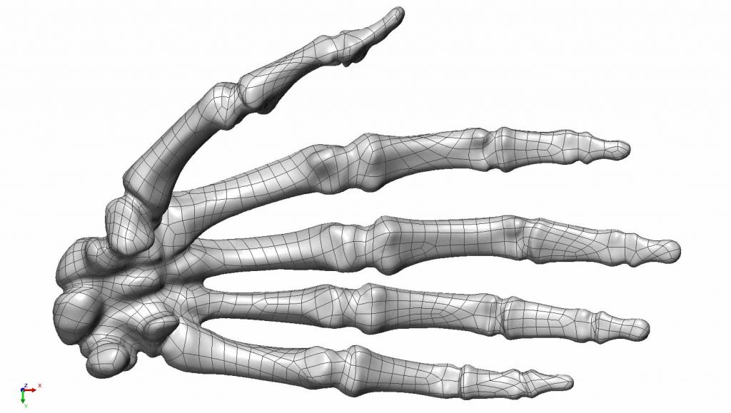
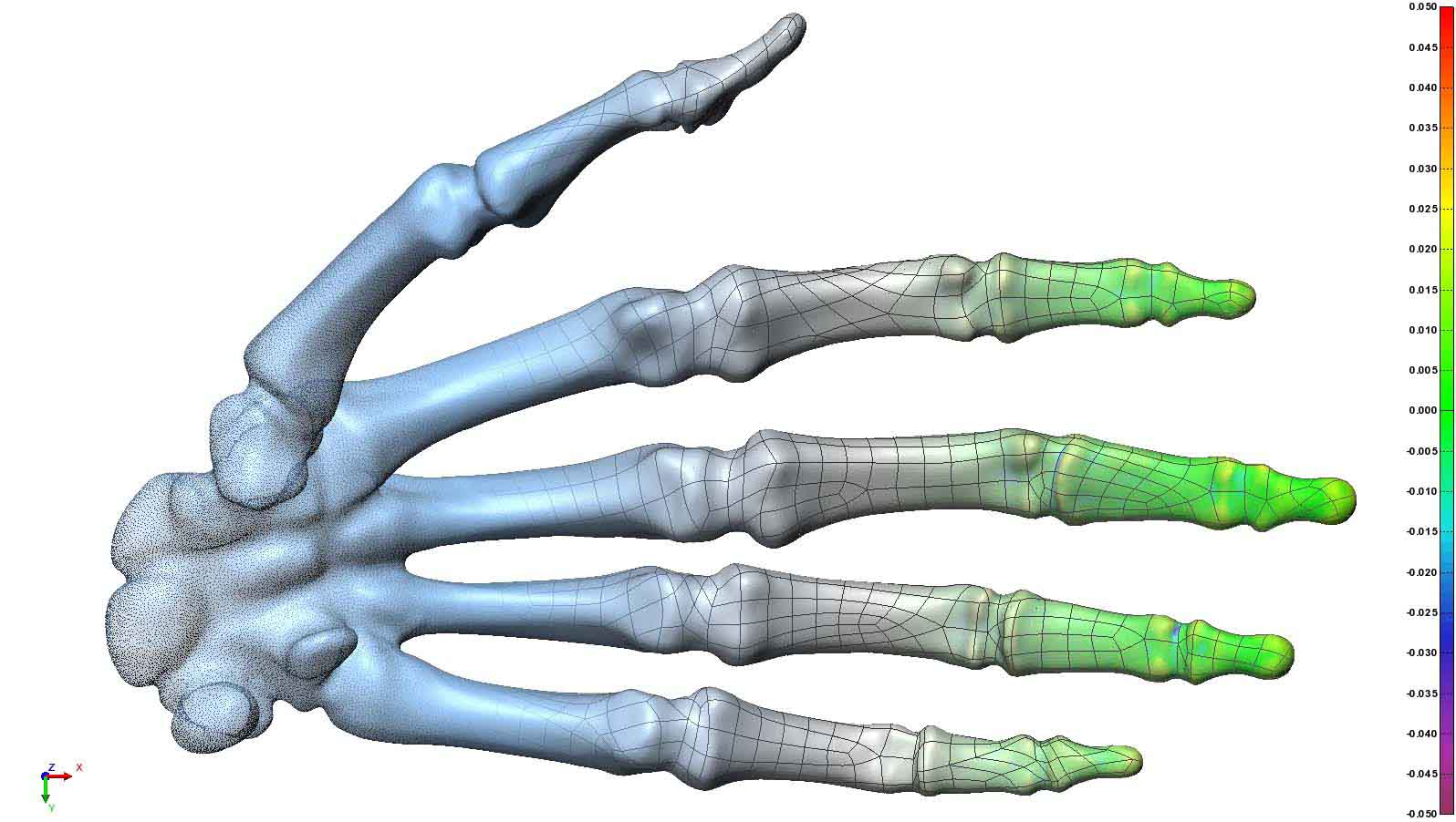
Surface Wrap
Simple Solid Models are CAD models that have been automatically surfaced in certain Scan to CAD softwares like Geomagic Design X.
The benefit to auto-surfacing is that you have a CAD model made from a scan file very quickly and with very high accuracy. This method is primarily for free form, indeterminable geometry. However, the models can be difficult to work with due to a lack of geometric features. For example, surfaces that are flat by design will have many surfaces with contours using this method.
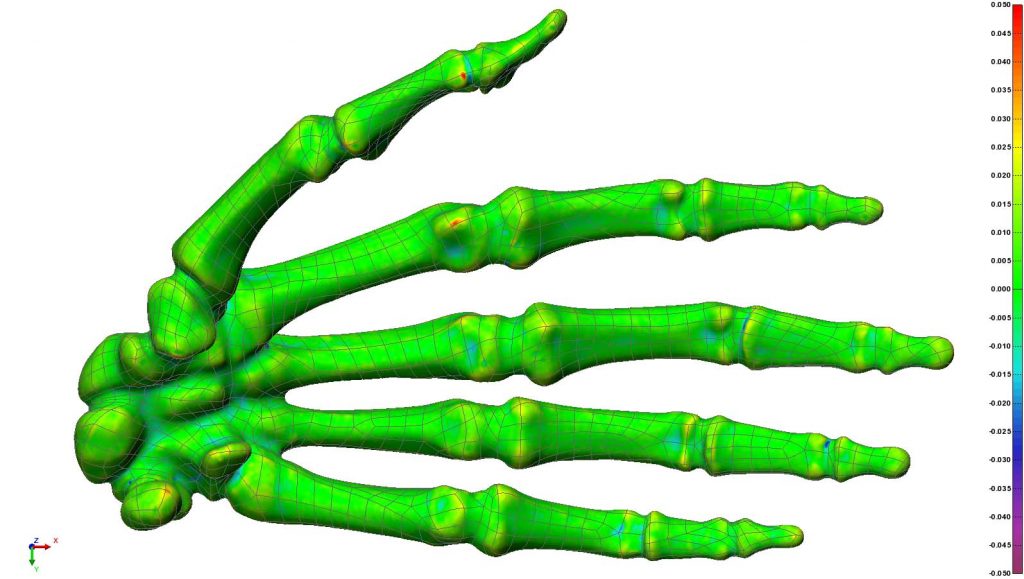
This hand example is the perfect candidate for auto surfacing. It’s free form but requires a high accuracy model. The deviation chart shows +-.05mm.
Parametric CAD Model
Parametric Models are models created manually, inspired by the scan file while incorporating design intent. This design intent can come from documentation like drawing specifications, or by the designer of the model. The models have a history based feature tree for editing, and driven modification where changes to features force changes to related features.
While no part or scan file is perfect, parametric modelling offers the ability to correct these imperfections. For example, perfect hole patterns can be implemented, planes made parallel, and diameters rounded to reasonable sizes. New features can be incorporated and parametric modelling ensures models will assemble properly.
We often use parametric modelling to incorporate modified features into an existing model. This modification allows the part to function better but can be difficult to quantify without scanning.

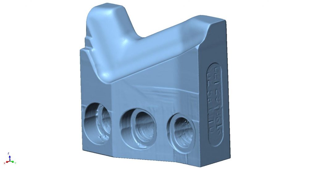
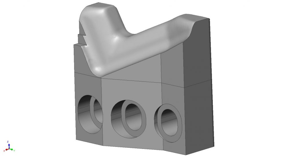
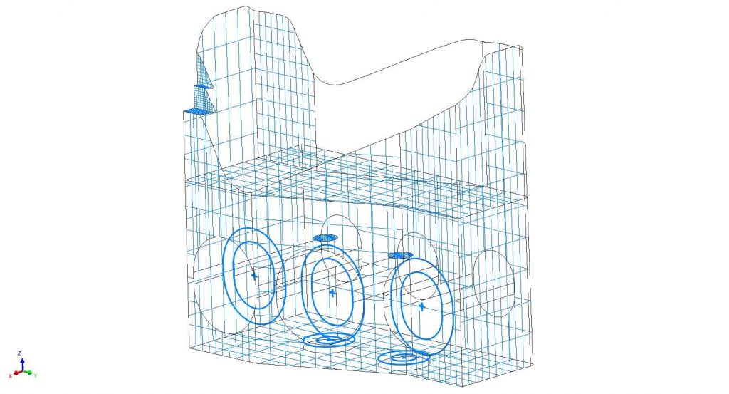
Hybrid CAD Model
Hybrid modeling combines the strengths of auto surfacing and parametric modelling.
We see applications for this often with die steel repair where the steel forms something with complex profile, but is assembled on a block that requires perfect surfaces.
In this example we have a block with free form surfaces near the top. The free for is a mesh fit that has been incorporated into the parametric block.
Feature Data Set
A feature data set is a common way to merry together many measuring devices that use different software. We often export nominal or measured features in .iges CAD format to our customers or coworkers. By doing this we know the same features are being measured or used.
It’s also an extremely fast (cheap) way to provide 3D data to our customers for various purposes like coordinate systems, feature locations, and 2D profiles and 3D polylines.
Volume File
Volume files are the raw data produced using industrial CT technologies. From these volumes, geometry can be exported into mesh files for dimensional inspection & reverse engineering, or slice imaging through the part can be performed to locate defects like fractures and porosity.

