


Measuring GD&T Profile with Confidence in PolyWorks
Maintaining Confidence While Measuring Profiles
A key component of being an ISO:17025 Accredited Lab is proving the capabilities of our equipment and technicians, and having absolute confidence in the data we produce. Traditionally, there has been a point of friction between CMM & Scan methodology due to the nature of how data is produced. Scanning technology is very good at investigating parts and offering the full picture of what may be happening. However, like using too few points via CMM, using too many points via scan can also mislead the user into making unnecessary decisions.
Below shows the model & scan file aligned in the same workspace and the resolution of the features of the scan file. Without our Nikon XTH 225 ST this part would be an absolute nightmare to scan and would likely have been measured via CMM.
Profile as T Value
Every once in a while we have clients request that we provide profile in min/max data sets, or as a single value derived from 2x Max Deviation. While this 2x Max Deviation method is per the ISO standard, offering a single numerical value for profile is typically inadequate, offers hardly any useful information, and can be entirely misleading of the true picture of the feature. We strongly suggest providing T Values or Surface Deviations over or in conjunction with these other methods of reporting.
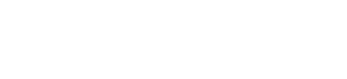
Having a complete data set for measurements is a double edged sword. We are able to see a full picture because we have complete data. However, this complete data is not always perfect, or may allow us to inadvertently use data locations we should not. The below example’s min/max/profile values are derived from edges, an ejector location, and a pin sized defect.
Parameters for Data Collection
In the example below a CMM may use three or four point locations to derive a plane or measure profile; the programmer will intentionally avoid the ejector location. If that ejector location is not in the CAD model, PolyWorks plane extraction will have a very difficult time avoiding this, and will provide “bad” data by using it as a high point, and the pin mark as a low point. I say “bad” because, while these locations are true form error, if I marked the profile out of tolerance because of them my client would go find a more reasonable metrology lab.
Because of dust, minor imperfections, curling data near part edges, and incomplete scan data, we NEVER use or recommend using the GD&T Profile Control in PolyWorks. While you can adjust extraction parameters like boundary exclusion and outlier rejection to mitigate some of this bad data, from part to part parameters may need to be changed and, thus, would not be considered repeatable.
Below we have visualized how important parameter adjustments are. You’ll noticed a profile difference of more than .5mm.
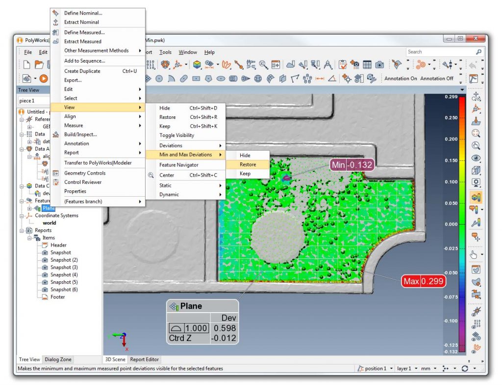
Extracted Versus Defined Profile
Heat maps and deviation charts along with repeatable profile locations through Surface Profile Points are the only way we measure profile using PolyWorks. Our experience is that the GD&T Profile Control is too difficult to control and will often mislead our clients.
Below you will see the difference between the GD&T Profile Control of an extracted versus a defined three point plane are.
