


Understanding GD&T Flatness in PolyWorks 2020
Reverse Engineered Model & CT Scan Files
Every time we produce a reverse engineered model we include with it a report detailing any deviation between the sample and model.
This COVID-19 prototype assembly was particularly difficult to model because its thin walls created significant twist across the part. The purpose of this post is to demonstrate what flatness is and how it is measured in PolyWorks.
GD&T Flatness
Flatness is a GD&T control that quantifies how flat a given surface is. It is not measured relative to a datum; instead it is relative form control.
To measure Flatness in PolyWorks:
- If using a model, define the nominal plane
- Define the measured primitive of that plane through extraction, probing, or construction from other features
- Measurement parameters are critical. Pay close attention to boundary exclusion, max angle, and outlier rejection
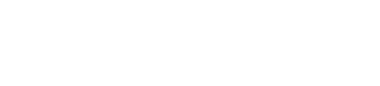
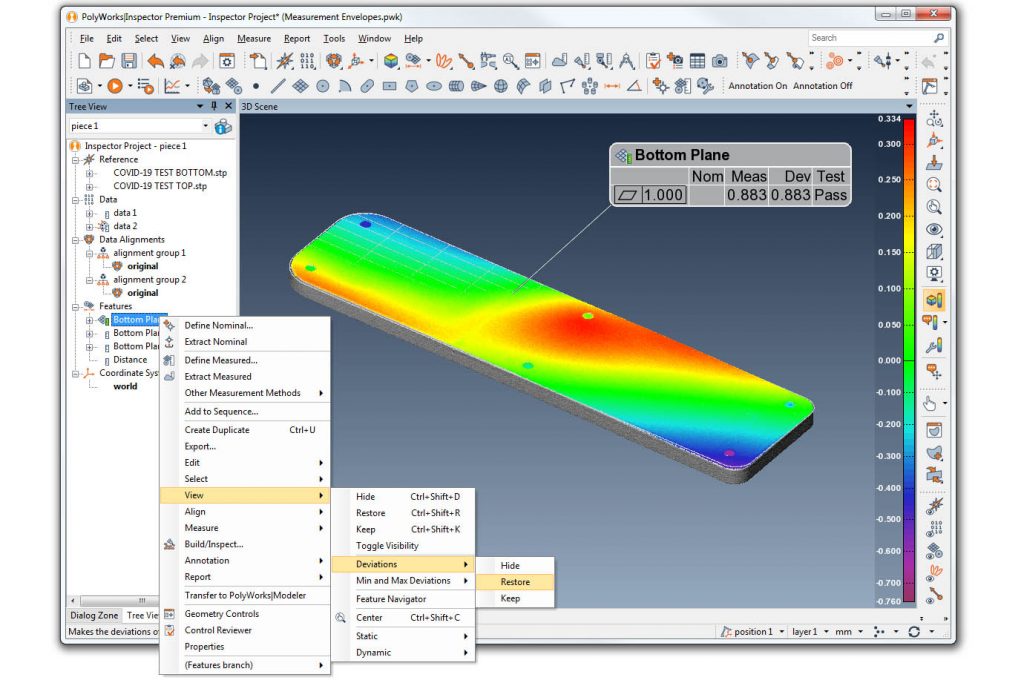
- Right click the plane and go to Geometry Controls
- Add Flatness from the GD&T Control tab
How is Flatness Calculated?
Flatness is simply a distance measurement. However, this distance is derived from two parallel planes. One plane becomes primary and fits to the highest (or lowest) measured points of the surface, and the other plane fits to the opposite, furthest measured point while simultaneously maintaining parallelism to each other.
Visualizing Flatness
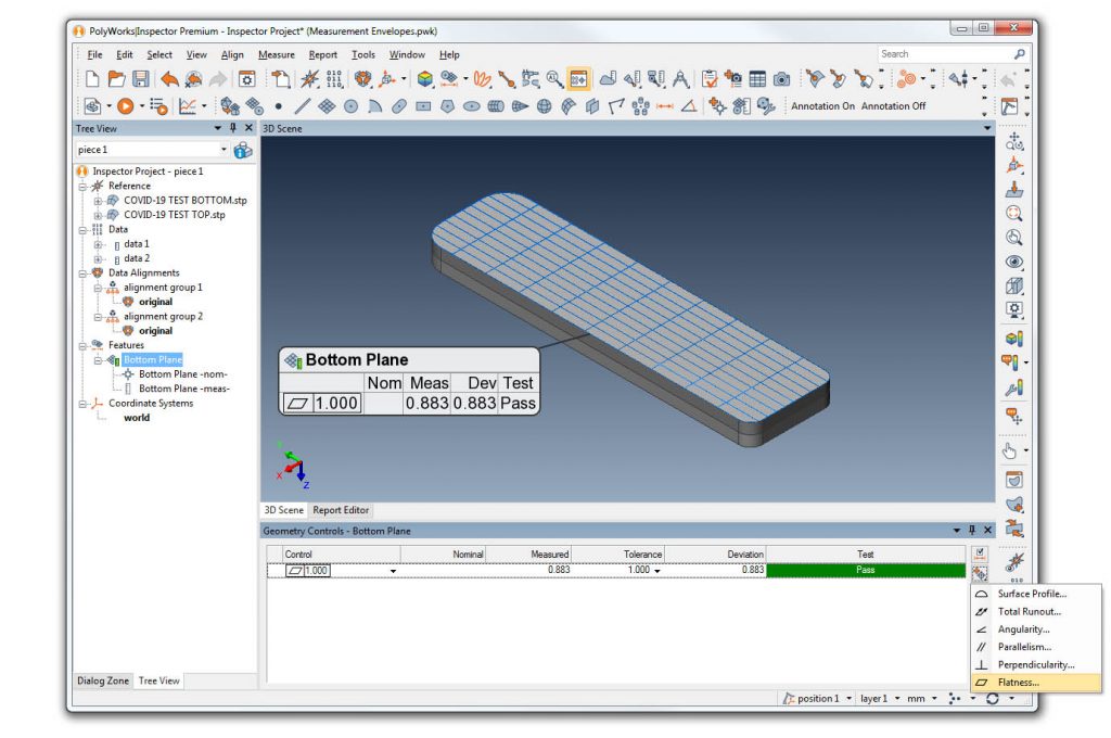
PolyWorks helps the user visualize this measured distance with a tool called Measurement Envelope. You can create the high and low planes from inside the Geometry Controls tab. However, it is important to know these features are not repeatable; you will need to manually create measurement envelope features for each piece in your program.
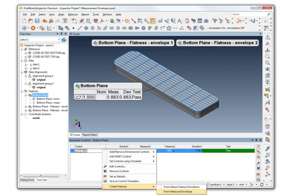
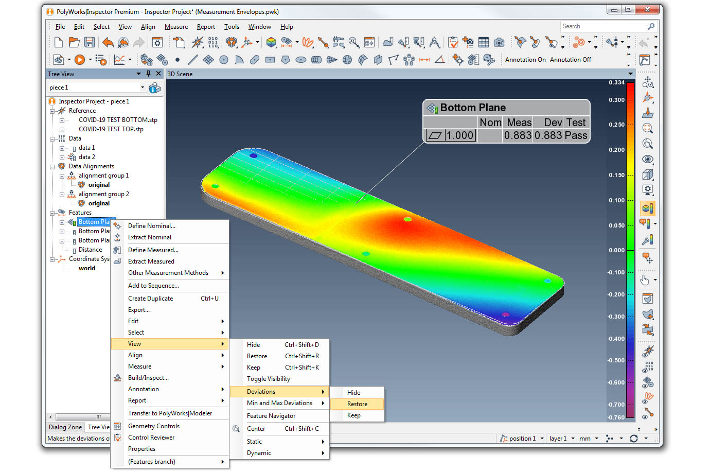
Envelope 2 is the plane derived from the highest three points. Envelope 1 is the plane parallel to Envelope 2 at the lowest single point. Notice how the distance between the two parallel planes matches the original Flatness deviation of .883. On a part this small and thin, that is a significant form issue.
Pairing Profile with Complex GD&T
On their own, many GD&T controls like Flatness are relatively useless. They may tell you if the part is in or out of specification but do not tell you how to fix the problem. Often we pair profile measurements with Flatness to help our clients understand how to make proper adjustments.
Below we demonstrate a fast way to understand the profile of the plane in question.
PolyWorks 2020 GD&T Update
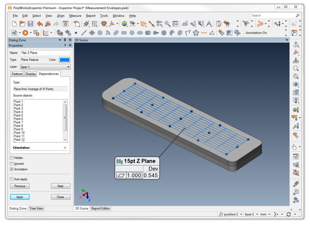
One of the best changes to PolyWorks 2020 is the ability to measure GD&T from constructed features. Previously, to measure flatness you would need to extract the plane from a scan file or probe the measured points. Now, you can define exactly where these points for flatness are derived from automatically.
Below is an example of defining exact point locations using Profile Points, constructing a plane from these points, and measuring flatness.
