


The Affects of Compounding Error
Recently we ran into a prime example of Compounding Error. Compounding Error has created problems for metrologists and engineers alike, and manifests in many ways. Its something that comes up regularly and is difficult to articulate with words alone.
What is Compounding Error?
Metrology is the study of measurement, and when one measures they are looking to learn the size, position or form of something. Typically this size or position is referenced back to a known value and the difference is called deviation. Compounding error is when deviation of one feature, or the process used to measure that feature, directly affects the measurement of another feature. There are best practices metrologists use to control compounding error but sometimes it is not possible. Per Haven Metrology’s accreditation if there is an uncertainty in the values we’ve measured we must either note this uncertainty or refuse measurement.

Here is an example of inevitable compounding error. The four highlighted radii must be measured, but as features they only make up approximately 5% of a total circle. A standard circle is measured with at least three points. Ideally, these three points would be equally spaced 120 degrees radially (3 points x 120 degrees = 360 degrees, 5 points x 72 degrees, and so on) but in this situation we can only space these three points inside of an 18 degree zone.
There are three inevitable issues with this. First, all measurement equipment has its own allowable error. Second, all measured features have their own deviation. Third, there are external factors that must be considered and could be outside of ones control. Any given variable, from a piece of dust, to temperature, to part set up, and machine error, could affect where these points actually measure. When you space the points out equally you are including one method to control these variables. When you cannot space the points out equally or use more than three points the size of the circle becomes more susceptible to these variables.
Visualizing Compounding Error
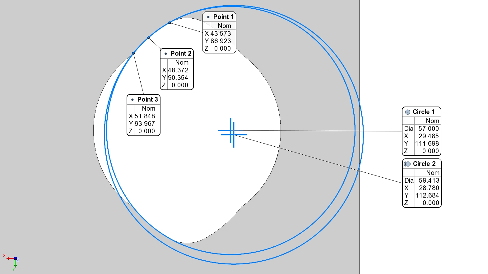
Above is a demonstration of two scenarios. Hover and press the navigation buttons to view the differences. The first image is with the three points spread out on an 18 degree 28.5mm arc. The second image, with two circles, shows what happens when just one of these points has a 50 micron (~2 Thousandths of an inch) deviation in just the X Axis. Look closely at the X value change between images. Because of this seemingly insignificant change in point location, the overall diameter grows from 57mm to approximately 59.5mm. That’s a compounding error of 5000%! 50 microns has transformed into 2500 microns of deviation for the measured diameter. If this arc was a datum, or its center point critical to the measurement of other dimensions, you’d see the effect of compounding error by adding millimeters to relatively small lengths.
Below is a demonstration of the same arc with the same first two points. The third point has been spaced further radially, but in the second image 50 microns has also been added to the X Axis. However, while there is still a difference in the diameter, it has been greatly reduced. This is because, as you move around the circle, the effective deviation is split between both the X & Y axes. To find the same deviation of 2.5mm in the diameter deviation in just the X axis of Point 3 would need to move nearly 3mm or 60x as far!
Creating a strong average of points and spacing them out evenly creates a more stable measurement method and environment. Measured ranges will decrease, unnecessary variables will be ruled out, and you’ll have confidence that you’re actually measuring your part and not the affect of a piece of dust. At Haven Metrology we put this knowledge and other best practices into use every day. Use our experience and understanding of metrology to your advantage.
