Suspension Measurements & Additional Components
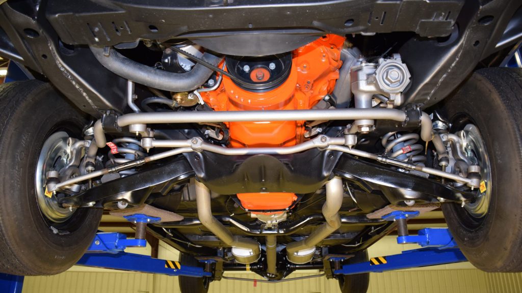
This versatility made our Faro Arm Quantum S the ideal choice for this project: measuring the suspension system on a rebuilt Chevelle. Our directive was to measure the locations of all joints and intersections back to an alignment made from the Sway Bar and Wheel Centers so that the data could be input into a separate software for virtual testing.

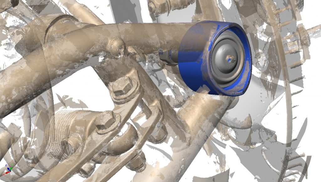
Rather than simply probing out dimensions we opted to also scan for visual aid, to have additional data for later, and to assist in accurate dimensional extraction. Because of the size and complexity of this project several scans from different positions were required. Each scan and associated measurements were gathered and then aligned back to a common coordinate system. Below you can swap between two images to see the compilation of seven scans, and then the post processed phase where they were merged together and cleaned of peripheral data.
The difficulty with measuring joints in a completed assembly is that the critical data is behind bolts and wedged between different components. To overcome this obstacle we had the unassembled components sent to our shop to be individually scanned using our high accuracy Zeiss Comet 6 system. Because ball joints were uniform in this assembly we scanned one and fit it back into all locations. However, the ball joint also needed to be disassembled in order to measure the center point of the internal sphere.
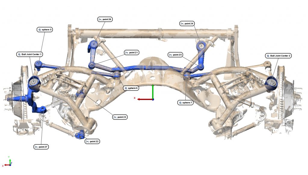
This sub assembly is then fit back into the overall suspension project at each location.

Below are all of the individual components that were fit back into the overall assembly. The mating points for each piece were defined and their coordinates referenced back to the overall alignment to understand where they were located in the overall suspension.

To understand some of the methods for completing this project visit our PolyWorks Guides page. Here you will be able to visualize best practices like selecting specific data for complex measurements found in our Critical Hotkeys Guide.


